YoungJooKim_GenerativeDesignComputing
Sunday, October 31, 2010
Monday, October 25, 2010
Sunday, October 3, 2010
project2_2d pattern
_ process
* 4 variables
1. 1st attractor point for a radius of polygon
2. 2nd attractor point for a rotation angle
3. a divider to reduce the distance between grid points and attractors
4. a slider bar for the decision of polygon shape

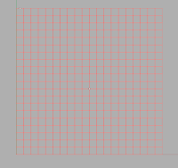
started with a rectangular grid, which is defined by 4 slider bars, in the domain of (20, 20) only in integers with the step size of 1. then set up the distance between one point and each grid point for the radius of each polygon, which works as the 1st attractor point. the distance is too long, so set up a divider to fit each polygon in the grid system. here, the polygon is set as a rectangle, which is defined by the slider bar to decide the shape of it.
next step is rotating each rectangle. the angle of rotation is also set up similarly to the way how the radius of each rectangle is done. the 2nd attractor point is used here to measure the distance between the point and each grid point so that it can define the angle.
_variations
1. attractor point setup

2. polygon setup

3. divider setup
* 4 variables
1. 1st attractor point for a radius of polygon
2. 2nd attractor point for a rotation angle
3. a divider to reduce the distance between grid points and attractors
4. a slider bar for the decision of polygon shape

started with a rectangular grid, which is defined by 4 slider bars, in the domain of (20, 20) only in integers with the step size of 1. then set up the distance between one point and each grid point for the radius of each polygon, which works as the 1st attractor point. the distance is too long, so set up a divider to fit each polygon in the grid system. here, the polygon is set as a rectangle, which is defined by the slider bar to decide the shape of it.
next step is rotating each rectangle. the angle of rotation is also set up similarly to the way how the radius of each rectangle is done. the 2nd attractor point is used here to measure the distance between the point and each grid point so that it can define the angle.
_variations
1. attractor point setup

2. polygon setup

3. divider setup
Tuesday, September 14, 2010
project1_paneling tools
started with 10"x10" flat surface and simply manipulated a flat surface into a somewhat complex surface with two concave and two convex shapes. then generated point grid (10x8) on the surface. to exaggerate the concave and convex shape, modified the grid pattern by using the shuffle grid function and created a dense pattern around the concave and a scattered pattern around the convex. at the end, the panel was created through the custom pattern design.
the process of creating a digital model was pretty fast, but the process of making a physical model took much longer than i expected. there were too many pieces and i did not make any mark/number on them, which complicated the process very much. so it was difficult to reproduce the exact same angles and shapes that the digital model.
Subscribe to:
Comments (Atom)


